


DC 120v 500A LCD Combo Meter Voltage current KWh Watt Meter 12v 24v 48v 96V Battery Capacity Power monitoring AUST STOCK FOR IMMED DELIVERY
Regular price
$99.99
 What's this?
NOW 500AMP
🇦🇺AUSTRALIAN STOCK DESPATCH USING AUSTRALIA POST
PRODUCT DESCRIPTION
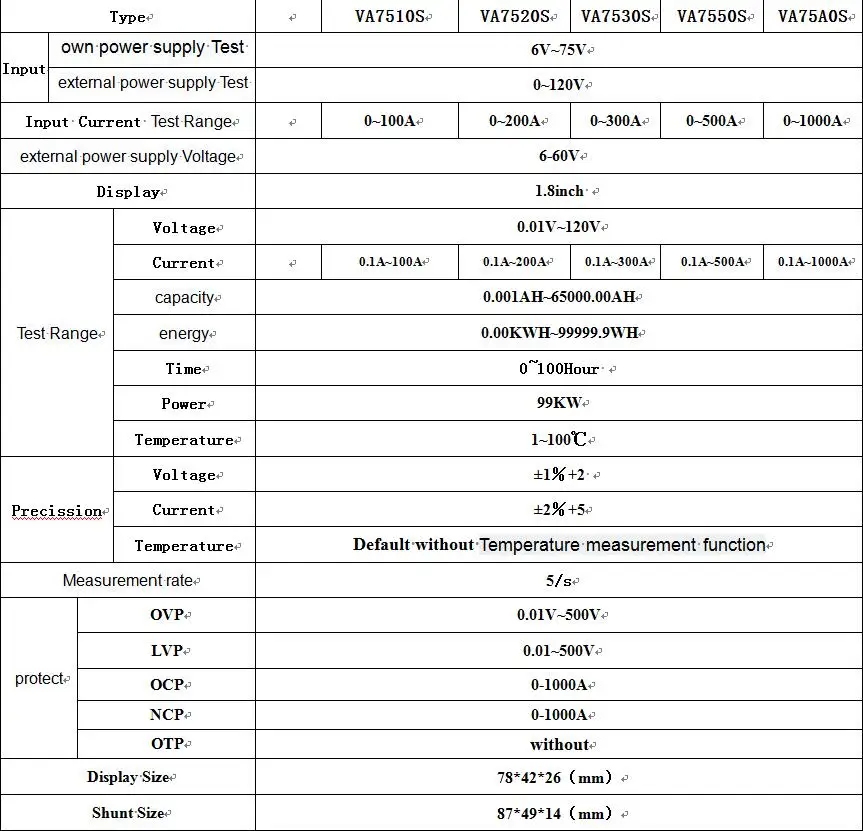
It is a basic multi-function instrument that can display various physical parameters such as voltage, current, power, capacity, energy, and operating time in real time. Overvoltage, undervoltage, overcurrent can be achieved through reserved relay interfaces. The meter uses 1.8-inch color LCD as a display, display data more comprehensive, clear and easy to observe. This meter is ideal for applications that require monitoring of the output voltage and current as well as applications such as charging and discharging batteries.
CHARACTERISTICS
1. The bidirectional detection current makes it easy for the user who detects the charge and discharge to detect the bidirectional current without changing the wiring direction.
2. Power-off memory function, able to memorize the number of AH and WH before power off after power off, which is convenient for observation and measurement.
3, time and AH number clear function, does not affect the next measurement.
4. The number of AHs can be filled up without affecting the direct discharge measurement.
5, voltage, current, charge capacity AH number, WH number, time, power at the same time display, display information is comprehensive and clear.
6, with output off function keys, flexible open or shut off the output.
7, with over-voltage, over-current protection.
8, when necessary, you can turn off the LCD display, reduce product power
Notice:Default without Temperature measurement function
SHIPPING DETAILS
💁🏼♂️This item will be sent by AUSTRALIA POST and a tracking number will be provided.
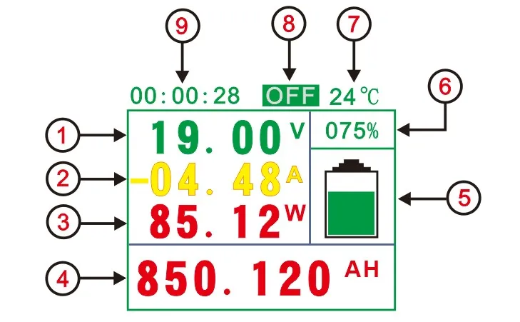
1 measured voltage value
2 Measured current value
3 measured power value
4 Accumulated capacity or energy value
5 Battery Remaining Capacity Progress Bar
6 percentage of battery remaining capacity
7 Measured temperature(Default withTemperature measurement function)
8 output status display
9 Total running time
10 Empty
Instructions
1. AH, WH display switch, click to switch to display WH number, click to switch to display AH number.
2. Press OK key to enter the system parameter setting interface, then press OK key to switch the type of setting parameter. The set parameters include BAT, BPC, OPP, OVP, LVP, NCP, OCP, OTP, ADS, TTL, CLR, DTE. , Click to change the parameters, after the parameters are set, press OK to exit the parameter setting interface.
Third, function introduction
1, "BAT" battery capacity value setting, this parameter is to set the battery measured total capacity.
2, "BPC" battery remaining capacity percentage, can be set according to the value of the remaining battery AH
4, "OVP" set over-voltage protection value, if the OVP value is set, when the actual measured voltage value is greater than the set value, it will prompt over-voltage, and cut off the relay (self-provisioned).
5, "LVP" set over-voltage protection value, if you set the LVP value, when the actual measured voltage value is less than the set value, it will prompt undervoltage, and cut off the relay (self-provisioned).
6, "NCP" set over-voltage protection value, if the NCP value is set, when the actual measurement of the charging current value is less than the set value, it will prompt over-current, and cut off the relay (self-provisioned).
7, "OCP" set over-voltage protection value, if the OCP value is set, when the actual measurement of discharge current value is less than the set value, it will prompt over-current, and cut off the relay (self-provisioned).
8, "OTP" set over-temperature protection value, if the OTP value is set, when the actual measured temperature value is greater than the set value, it will prompt the temperature, and cut off the relay (self-provisioned ,Default without Temperature measurement function).
9, "ADS" communication address code settings. In multi-machine communication, multi-machine communication is achieved by setting the address code.
10, "TTL" instrument default relay output power state, normally open or normally closed.
11, "CLR" no-load current clear function, if the actual no-load current is zero
Connection mode
1) its own power supply wiring diagram
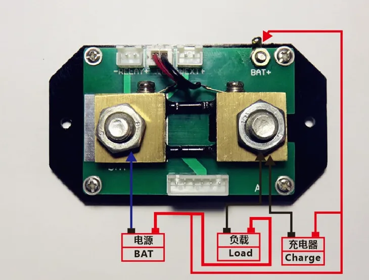
Note: If the voltage range of the tested battery (power supply) is between (6-75V) during the normal operation, it can use its own power supply wiring mode. First, adjust the jumper cap of the power supply selection interface to “2W”, and then connect it. The positive pole of the battery (power supply) is connected to the voltage measurement port “Bat+”, and the negative pole of the battery (power supply) is connected to the shunt “BAT-”. The positive and negative poles of the power supply should not be connected wrongly or reversed. Connect the positive pole of the battery (power supply) to the positive pole of the load, and connect the negative pole of the battery (power supply) to the negative pole of the load through the other end of the shunt; the positive pole of the charger is connected to the positive pole of the battery, and the negative pole of the charger passes through the shunt. One end is connected to the battery (power supply).
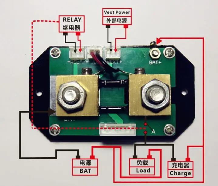
(2) External power supply wiring diagram
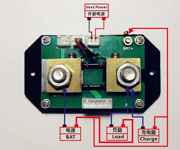
Note: If the voltage range of the tested battery (power supply) during normal operation is not between (6-75V), the external power supply connection mode can be used. The external power supply voltage range is (6-75)V. The power supply selection interface jumper cap is firstly used. Adjust to "3W", then connect the positive terminal of the battery (power supply) to the voltage measurement port "Bat+" at the time of connection, connect the negative pole of the battery (power supply) to the shunt "BAT-", and the positive and negative poles of the power supply should not be connected. Wrong or reversed. Connect the positive pole of the battery (power supply) to the positive pole of the load, and connect the negative pole of the battery (power supply) to the negative pole of the load through the other end of the shunt; the positive pole of the charger is connected to the positive pole of the battery, and the negative pole of the charger passes through the shunt. One end is connected to the negative pole of the battery (power supply) phase.
3) Electrical relay wiring instructions
DIY Supplies: Electrical
Display Type: Digital Only
Dimensions: Voltage current KWh Watt Meter
Power Supply: DC